FM SYNTHESIS
1. Introduction
FM has a bit of a bad reputation for being unnecessarily complicated, but we’re
going to see that it really isn’t that bad.
The major difficulty with FM is that although it appears to have similar controls to an analogue style synth, it is a different form of synthesis and works in an entirely different way. It can create vastly different sounds, ranging from growly basses, to clangarous bell sounds right through to ear ripping digital noise, and all this can be created from just 2 oscillators, pretty phenomenal when you think about it. This week we are going to take a look at FM through two FM synths in Logic X (EFM1 and Retro Synth) before taking a brief look at Native Instrument’s FM8, a monster of a synth that brings FM bang up to date!
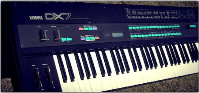
(The DX7, not the first FM synth but the most commercially successful & featured on countless
records in the 80’s!)
FM synthesis was discovered in 1967 by John Chowning, a professor at Stanford University. In 1973 Stanford licenced the technology to Yamaha (it’s still one of it’s most lucrative licenses!) But it wasn’t until the early ‘80s and the introduction of the Yamaha DX7 that saw a mainstream, acceptance of FM. FM synthesis had a reputation for being fearsomely complex and the large majority of DX7s still had their original presets on when they were sold by their owners, as the interface and FM synthesis were just too complicated for most people!
2. What Is FM?
FM or Frequency Modulation occurs when the frequency of an oscillator is
modulated by the frequency of another oscillator. Theoretically speaking if you
were to grab hold of the frequency control of your synth, and move it up & down
over 15 times a second, FM synthesis would take place. But to be honest this
really hurts if you try to do that, so the easiest way is to use another oscillator!
You might not have realised but we already looked at slow form of Frequency Modulation in week 2, when we routed an LFO to the Frequency to create vibrato effects. For FM synthesis to happen, we need to speed that LFO up to
oscillate above a rate of 15 Hz, and then amazing things start to happen. From just 2 simple sine waves, FM is capable of creating loads of different harmonics. These harmonics are created according to mathematical functions and are highly predictable, but don’t worry we’re not going to go there as its way beyond the scope of what we’re covering in this course! If you are interested, however, and have a good understanding of advanced maths then Sound on Sound ran several articles on FM synthesis
http://www.soundonsound.com/sos/apr00/articles/synthsecrets.htm
Looking at the diagram below, we actually only hear B – we can’t hear oscillator A as its output is routed to B’s frequency, input but we can obviously hear the effect it’s having on B. In FM synthesis we commonly refer to any oscillator that is modulating another as a Modulator, and any oscillator that we hear is known as a Carrier. We will look at these in more detail on the next page. Don’t worry if this sounds a bit alien at the moment, we’ll be reinforcing the important elements throughout the lesson.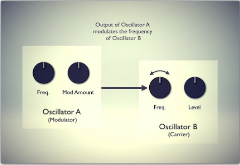 This shows you how FM Synthesis basically works

3. EFM1
The EFM1 has been one of Logic’s best–kept secrets and is so often overlooked (as are most of Logic’s synths!) but is capable of an incredible range of sounds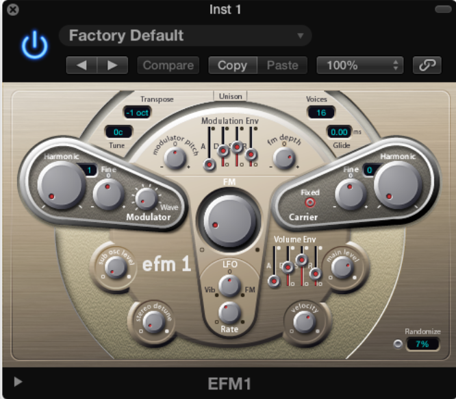
The heart of the EFM1 is relatively simple; it has two oscillators, a Modulator and a Carrier. The Carrier outputs a simple sine wave but the Modulator is capable of producing a range of different waveforms via the Modulator wave
knob. This creates additional harmonics that directly affects the frequency content of the carrier. On the Carrier, the Fixed button disconnects the carrier frequency from keyboard, pitch bend and LFO. This means that you can
produce a carrier tone that is free from those sources.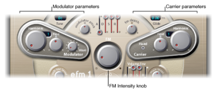
Point Blank LTD 6
By rotating the Harmonic knob in each section, the Modulator and the Carrier respectively can be set to any of the first 32 harmonics. The tuning ratio this creates between the two will significantly alter the base sound and it’s worth
experimenting with this to see the wide range of sounds that are possible.
As a rule even tuning ratios will tend to produce more harmonic or musical tones, where as odd ratios will create more inharmonic overtones, which are great for producing the bell-like and metallic sounds that FM is renowned for!
Both oscillators have Fine tune controls that additionally alter the sound. By moving the tuning away from whole number harmonics, increasing amounts of inharmonic frequencies are produced. The Fine control allows you to set the pitch very precisely between the coarse settings. This can really expand the sonic potential when synthesising sounds using FM. At low settings it will create an effect similar to detuning, creating a thicker sound with some subtle movement. As you sweep through, it will create in harmonic frequencies, and at different times the tuning will lock into a specific tuning e.g. a 5th and create a harmonic sound.
The FM intensity knob sets the amount of frequency modulation from the modulator to the carrier, the greater the amount the more FM you have.
Now, remember the harmonic series from week 1?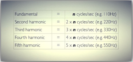
Harmonic Series from Week 1
For this example, set the Carrier Harmonic to zero and increase the Modulator Harmonic one at a time and listen to the results.
The harmonic knob tunes the oscillator to a specific harmonic number of the harmonic series, and is not unlike an octave or semitone tuning control commonly found on oscillators. The diagram above shows the frequency of the
different harmonics. We could also work it out in terms of notes, so if the fundamental was C3:
- Harmonic 1 = C3
- Harmonic 2 = C4
- Harmonic 3 = G4
- Harmonic 4 = C5
- Harmonic 5 = E5
So if you were to play C3 and adjust the modulator harmonic knob, it would play these notes – as you can see the intervals become smaller as we go higher in the harmonic series.
One of the crucial aspects of FM Synthesis is the relationship or ratio between the frequency of the Modulator and the Carrier. If this Harmonic Ratio is 1:1 then as we increase the modulation amount the sidebands or harmonics that are created correspond to the harmonic series, pretty neat eh?
Sidebands
Any additional frequencies that are created through modulation synthesis are often referred to as Sidebands. They could also be referred to as harmonics or partials
EFM1 Modulation
As with most synthesisers a large part of the power lies in their modulation abilities, that is how you can alter parameters over time.
This is particularly true with FM as the different modulators available have a direct impact on the change in harmonic content. On the surface only having one modulation envelope and one LFO would seem to be limiting, but
remember this is FM! With both affecting the overall timbre there’s a whole lot of sounds to be had.
The modulation envelope is an ADSR envelope that is triggered every time a MIDI note is received. Whilst it appears to share similarities with the same envelope on a subtractive synthesiser it’s impact on the overall sound is far more dramatic at increasing levels of FM depth.
The FM depth controls the impact of the modulation amount on the FM intensity. If you move the control counter-clockwise from 0 it will invert the effect of the envelope (attack goes down, decay goes up)
By increasing the modulator pitch you can control impact of the modulation amount on the FM intensity. For example, you can create classic FM type falls by turning this all the way to the right and increasing the modulation decay to full.
Finally, the LFO knob has a dual function. Turning it to the left produces a vibrato type effect and turning to the right applies the LFO to the FM intensity.
4. Retro Synth (FM Mode)
Introduced in Logic X, Retro Synth is synthesiser that uses three types of synthesis- subtractive, wavetabling & FM. In terms of its overall architecture it adheres to the basic model of Oscillator! Fllter ! Amplifier, with modulation
duties taken care of by a filter and amplifier envelope and a single LFO with vibrato.
Closer inspection of the FM page shows a single oscillator (the carrier) that can be modulated by several sliders and there is a mix slider that, unusually, allows the outputs of the Carrier and Modulator to be blended.
The Oscillator Section
The basic operation of FM in Retro Synth is similar to that of the EFM1. There is just a single Carrier (a simple sine wave) and a single Modulator that produce sound through the manipulation of the tuning ratio between the two. The
difference is in how this is implemented.
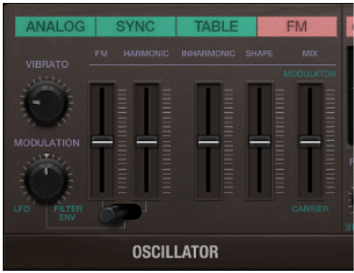
As you can see in the above diagram, the Modulator consists of several sliders that control various aspects of the Modulation oscillator.
FM: This slider controls the amount of FM required
Harmonic: controls the amount of harmonic frequencies generated by the modulator.
Inharmonic: controls the amount of inharmonic frequencies generated by the modulator.
Having separate sliders for the harmonic and inharmonic frequencies is a great advantage as it allows you to dial in the exact amount of each that you require.
The Shape: This slider controls the wave shape of the Modulation oscillator. Changing the wave shape can drastically alter the tuning ratio, so best to leave this alone if your sound requires a subtle adjustment!
The FM & Shape sliders are interactive and adjustments of each will create a range of tones with more or less harmonic / inharmonic content.
FM Modulation
The source and intensity of the modulation of the Modulation oscillatare handled by the Modulation knob, with clockwise rotation leading to increased amounts of Filter envelope modulation and counter-clockwise rotation leading to increased amount of LFO modulation.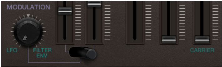
The Modulation switch acts as a routing source for the Modulation amount
knob:
• The left switch postion routes it to the FM amount,
• The centre switch position routes it to both the FM amount and the Harmonic content simulatneously
• The right switch position routes it to the Harmonic content
Both the EFM1 and the Retro Synth offer a good introduction in to what FM has
to offer. The simplicity of the FM implementation enables useable and
interesting sounds to be generated with relative ease.
5. Operators and algorithms
So, you may be asking, where has FM got it’s fearsome reputation from? Well, one of the reasons is that it can be pretty hard to predict what sound you are going to get by moving any of the sliders or knobs. The slightest change
can drastically alter the sound, as you’ve probably found out by now!
The main reason for it’s reputation is the complexity of a full FM implementation which comes about from the number of operators and how they can be routed.
An operator in FM is essentially an oscillator. In basic FM the oscillator generates a sine wave, but as we’ve already seen there is nothing to stop the operator generating any kind of waveform and the more complex the waveform
the more drastically the carrier oscillator is going to altered. In both the EFM1 and Retro Synth you are limited to two operators (the Modulator and the Carrier) in a fixed configuration, which keeps things relatively simple.
The DX7 has 6 six sine wave operators that can be arranged and connected up in 32 different ways. Each of these arrangements is known as an algorithm and produces vastly different sounds.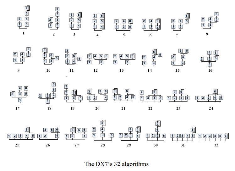 To further complicate things, each operator can be either a carrier or a modulator depending on the algorithm that is selected and on top of that it’s possible to have more than one carrier at a time– still with me??
You can probably now see where FM’s reputation comes from, but don’t worry, we’re going to de–mystify this by taking a look at one of the most powerful FM synths out there– Native Instrument’s FM8.
6.NATIVE INSTRUMENTS – FM8
The FM8 is a full FM synthesiser that has the DNA of the DX7 running right through it– so much so that it will play original DX7 patches!
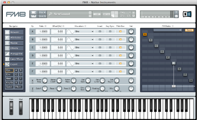
6.NATIVE INSTRUMENTS – FM8
The FM8 is a full FM synthesiser that has the DNA of the DX7 running right through it– so much so that it will play original DX7 patches!
The display breaks down into 4 ‘zones’:
• The Application control bar at the top
• The Navigator, for choosing the various editing windows.
• The Editing area, which displays the current editing window.
• The Keyboard, which can be triggered using the mouse.
The Navigator
The navigator is used to move around the different sections of FM8. In the upper part you can move between the different global options such as the Browser, Master, Arpeggiator and Effect sections. Additionally you can also
switch between Easy and Expert pages that give you different levels of complexity in using FM. The bottom part gives you access to all the windows that are available in Expert mode including windows for each individual operator
(A through F), two additional operators X and Z which allow for the addition of noise and wave shaping and filtering respectively. You can also get overal Pitch parameters and a window giving you a visual representation of the waveform and harmonics.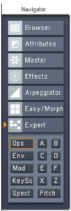
Easy/Morph Mode
To get you started the FM8 provides you with an Easy mode that gives you access to a set of macro controls that allows you to alter the overall timbre of the sound using both a timbre and an amp envelope, with controls to adjust
global timbre parameters like Harmonic content and Brightness.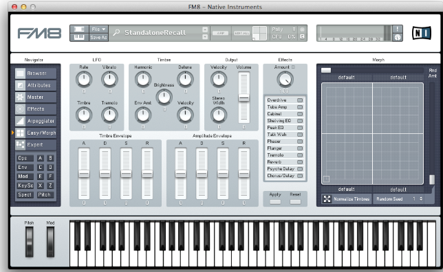
Additionally you gain quick access to the effects section and a morph pad that lets you move between four different sounds at once. You can drag and droppatches from the browser into the Morph pad icon in the Application Control
Bar.
Easy mode is a great way to get started and to get access to sounds roughly and quickly, but it’s time to roll up your sleeves and get stuck into Expert mode, this is where the fun begins!
Expert Mode
The different windows in expert mode give you direct control of the FM synthesis engine and they are accessed from the bottom of the Navigator. They are split into two groups:
• The global group (FM Matrix, Pitch and single Operator windows)
• An aggregate group that brings various parameters into one window
(such as the Operators or Envelopes windows)
Over the next few pages we’ll be looking at these windows in turn, so it’s worth
spending a moment selecting between them to get a feel for it.
FM Matrix
This is the heart of the FM8 synthesis engine and it provides you with a way of creating your own FM algorithms by enabling or disabling each Operator and additionally routing their outputs.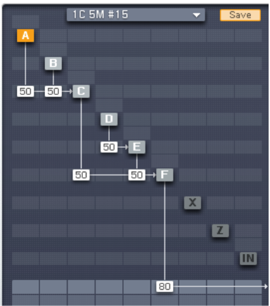
An Operator is switched on or off by right–clicking on its letter. You can select the relevant Operator by clicking in it, which will turn the symbol yellow and this will bring up the individual Operator window in the centre of the display (more about this later) Alternatively you can still select individual Operators from the Navigator.
The two rows of light grey boxes at the bottom of the FM Matrix window are routing for the audio output (top row) and panning of the Operator (Bottom row) Any Operator output routed to the top row will turn that Operator into a Carrier. Note that it is possible for any Operator to be both a Carrier and/or a Modulator at the same time!
To route the output signal of an Operator you click and drag up in the relevant box; for example, in the diagram above you can see how Operator C is modulating Operator F by 50. Not only can you route any Operator to any other Operator you can also feedback an Operator to itself and additionally there is an audio input (IN) that can be used to turn the FM8 into an FX unit.
The complexity of the routing at this stage may be a touch overwhelming so once you’re comfortable with the basic controls you can check out the preset algorithms available from the top of the FM Matrix. Click on the down arrow and a drop down list of a range of algorithms appears. Take time to peruse the list, making note of any algorithms that you like the sound of. You can also use the save button to keep any algorithms that you create.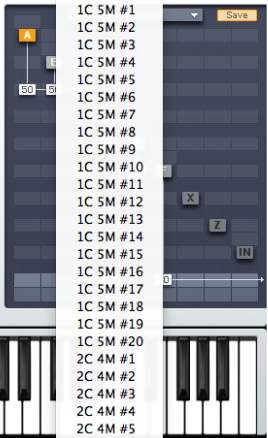
So to recap:
• Right-click an Operator to switch it on and off.
• Click and drag up to increase the value of a routing between Operators.
• Double-click a value to reset it.
• Click in the drop down list at the top of the FM Matrix to select preset
algorithms.
The Operator Window
For Operators A though F this window is identical. Here you can access all the individual parameters for the selected Operator including its Frequency Controls (via Ratio and Offset), the waveform, an amp modulation section (which is actually a subset of the Modulation Matrix page) and a multi–stage loop–able tempo–syncable amp envelope (with a variety of presets).
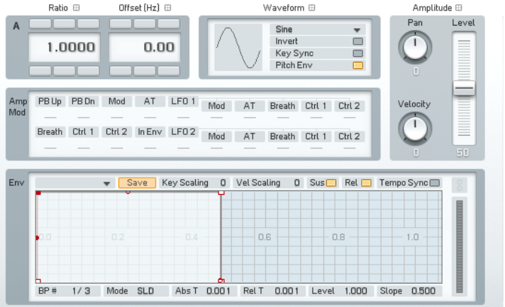
(Operator A window)
The envelope is represented graphically at the bottom half of the window. You can change the shape by clicking and dragging on a node on the envelope itself. New nodes can be created by right–clicking where you want the node to
appear and deleted by right–click it again. Through this you can go from simple AD style envelopes to ones that are
fantastically complex.
The window for Operator X provides access to noise and wave shaping options, to create all manner of distortion type effects.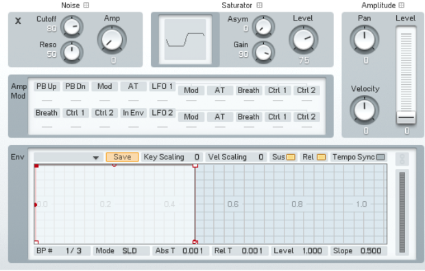
(Operator X window)
The window for Operator Z provides access to the multi–mode filter. Actually you gain access to two filters that can be combined in a variety of configuarions.
(Operator Z window)
The Global Windows
Clicking ‘Ops’ in the Navigator brings up a global window that shows all the Operators to together. More specifically it enable you to see the parameters for the Frequency and Waveform controls for Operators A through F and also the main controls for Operator X and for Operator Z.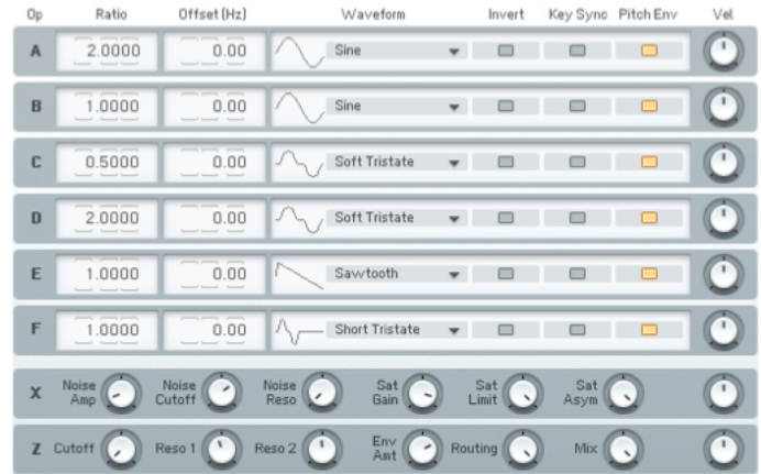
(The Ops Window)
Similar to the Ops window, the Envelope window shows you envelopes for all of the Operators in one place. Clicking anywhere on a particular part of the Operator envelope will auto zoom that envelope making it editable. This is great
for fine–tuning the envelopes against each other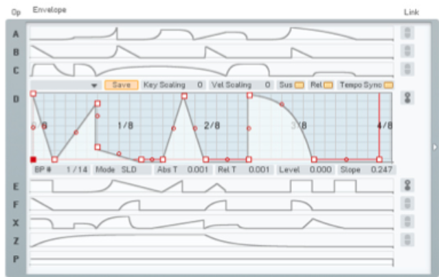 (The Envelope Window (note Operator D is showing)
The Modulation Matrix page gives you access to the entire range of modulation sources and targets available in FM8, including two LFOs. This matrix uses the same technique as the FM matrix to allow the routing of sources to targets (click and drag up/down)